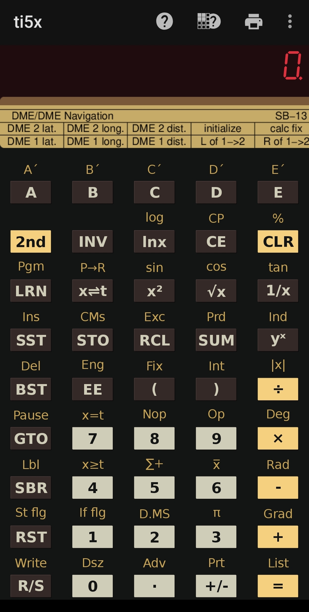
Calculate an aircraft's current geographical latitude and longitude (sometimes also called a fix) from the known positions of two DME stations, and the slant range distance from both of them. Optionally, enter the height of the aircraft above each DME station, which allows to correct the slant range into horizontal distance, and which may improve the accuracy of the fix.
This program is designed for experimental navigation calculations over distances and at altitudes typical of general aviation (GA). It uses an approximate planar model of the Earth's surface, with corrections for the convergence of meridians towards the poles, rather than full spherical or ellipsoidal geometry.
This approximation introduces systematic position errors that can become substantial over long distances. The magnitude of these errors depends on the geographical configuration and generally increases with distance. Consequently, the program is not suitable for the extended navigation distances typical of high-altitude airline operations.
|
⚠️ For educational and flight-simulation use only. Not suitable as a primary or safety-critical navigation aid in real aircraft. ⚠️ |
(a) If the absolute height difference (in feet, converted to nautical miles) is greater than the measured slant range (in nautical miles), which is physically impossible in reality (or a severe measurement error), the program rejects.
The program then corrects each measured slant range for its associated height difference, obtaining a horizontal distance.
If the horizontal distance is zero (indicating that the aircraft is directly above that station), there are no two distinct intersection points, which however are required for a valid fix.
(b) When L is the horizontal distance between the two DME stations and d1 and d2 their respective corrected horizontal distances to the aircraft, the two distance circles can have five geometrical relationships:
| Condition | Geometry | Result |
|---|---|---|
| L > d1 + d2 | Circles too far apart to meet (externally separated) | REJECT: no intersection |
| L = d1 + d2 | Circles touch externally at one point | REJECT: tangency; perpendicular offset h = 0 |
| |d1 − d2| < L < d1 + d2 | Circles cross at two distinct points | Proceed to the intersection angle quality check (see below) |
| L = |d1 − d2| | Circles touch internally at one point | REJECT: tangency; perpendicular offset h = 0 |
| L < |d1 − d2| | One circle lies inside the other without touching (internally separated) | REJECT: no intersection |
Intersection angle quality: Two intersections can still give an unreliable fix if the circles cross at a very shallow angle, understood as the angle between the two lines from the aircraft to each of the two DME stations.
This angle is folded into the range 0°-90°, because sin(α) = sin(180°-α); an obtuse intersection angle is equivalent to its supplementary acute angle.
The program rejects a fix if the folded angle is less than 5°. This rejects intersections near either external or internal tangency, even when the circles cross at two distinct points.
The error margin amplification factor is calculated as the reciprocal of the sine of this folded angle.
| Intersection angle | Error margin amplification factor | Assessment |
|---|---|---|
| 0° to <5° | ≥11.47× (undefined at 0°) | REJECT |
| 5° to <15° | 3.86–11.47× | Poor |
| 15° to <30° | 2.00–3.86× | Marginal |
| 30° to <60° | 1.15–2.00× | Good |
| 60° to 90° | 1.00–1.15× | Excellent |
|
⚠️ BEWARE: ⚠️ Contrary to my other programs, in this program the actual calculations are NOT carried out by pressing , but by pressing E'! Subtle difference, huge consequence! If you get a non-blinking zero in both X and T, you have probably pressed instead of E'! Press E' to calculate the positions. Then press for the LEFT position or for the RIGHT position. Also BEWARE that in order to initialize the program, you need to press D', and NOT E', or you may get meaningless or confusing results. |
To initialize for a new pair of DME stations, press D'; this also enforces Deg mode.
Enter the geographical coordinates of both DME stations, followed by the slant range distance for each of them.
Optionally, enter the height of the aircraft above each DME station with , or , which allows to correct the slant range into horizontal distance, and which may improve the accuracy of the fix.
| Key | Input / Output | Location | Format / Unit |
|---|---|---|---|
| D' | Initialize | Registers 1-28 | n/a |
| Input/output DME 1 latitude | Display (x) | DDDMM.mmmmm | |
| Input/output DME 1 longitude | Display (x) | DDDMM.mmmmm | |
| Input slant range distance from DME 1 | Display (x) | nautical miles | |
| A' | Input/output DME 2 latitude | Display (x) | DDDMM.mmmmm |
| B' | Input/output DME 2 longitude | Display (x) | DDDMM.mmmmm |
| C' | Input slant range distance from DME 2 | Display (x) | nautical miles |
| E' | Calculate fix | Display (x): intersection angle in degrees (0-90); Register t: error margin amplification factor | DDD.ddddddd; n/a |
| Output position LEFT of DME 1 to DME 2 directed line | Display (x): latitude; Register t: longitude | DDDMM.mmmmm; DDDMM.mmmmm | |
| Output position RIGHT of DME 1 to DME 2 directed line | Display (x): latitude; Register t: longitude | DDDMM.mmmmm; DDDMM.mmmmm |
| Keys | Explanation | Location | Format / Unit | Comment |
|---|---|---|---|---|
| Store aircraft's height above DME 1 | Register 17 | feet | mnemonic: '(' comes first | |
| Store aircraft's height above DME 2 | Register 18 | feet | mnemonic: ')' comes second | |
| Store aircraft's height above both DME 1 and 2, if both are the same | Registers 17 and 18 | feet | mnemonic: 'EE' is "double" |
Press E' to calculate the aircraft's two possible positions. If the geometry is acceptable, you can then retrieve the two positions, either the one to the LEFT of the directed line from DME 1 to DME 2 with ; or the one to the RIGHT of the directed line from DME 1 to DME 2 with .
After calculation, , , A' and B' retrieve their stored values instead of accepting new ones; and C', as well as , and , always accept new entries (in order to allow for quick successive fixes).
To change station coordinates, press D' and re-enter all data; initialization clears registers 01–28, including the stored heights, and sets Deg mode.
If you press or before a valid result has been obtained by E', or if the calculation has been rejected, then both and will display a zero in both the display and in t.
Note that not only does D' reset the flag for valid output and E' in case of a rejected calculation, but so do and C', as well as , and , i.e.,
whenever you re-enter a new slant range distance or a new height of the aircraft above the corresponding DME station. This prevents muddled results while allowing repeated fixes in rapid succession.
Simply press E' again.
After pressing E', the program displays the acute intersection angle (0–90°) in x and the error margin amplification factor in t.
The error margin amplification factor indicates how sensitive the calculated position is to errors in the measured distances; it is not an absolute position-error estimate.
If E' has rejected the fix, the program stops and shows a blinking "9.9999999 99" in the display (x), and t is set to zero.
The function can be used anytime after calling E' to display the intersection angle and the error margin amplification factor again, also in the case of a rejected calculation, if available (if not, zero and plus infinity will be shown as defaults).
| Key | Input / Output | Location | Format / Unit |
|---|---|---|---|
| Input/output DME 1 latitude | Display (x) | DDDMM.mmmmm | |
| Input/output DME 1 longitude | Display (x) | DDDMM.mmmmm | |
| Input slant range distance from DME 1 | Display (x) | nautical miles | |
| Output position LEFT of DME 1 to DME 2 directed line | Display (x): latitude; Register t: longitude | DDDMM.mmmmm; DDDMM.mmmmm | |
| Output position RIGHT of DME 1 to DME 2 directed line | Display (x): latitude; Register t: longitude | DDDMM.mmmmm; DDDMM.mmmmm | |
| A' | Input/output DME 2 latitude | Display (x) | DDDMM.mmmmm |
| B' | Input/output DME 2 longitude | Display (x) | DDDMM.mmmmm |
| C' | Input slant range distance from DME 2 | Display (x) | nautical miles |
| D' | Initialize | Registers 1-28 | n/a |
| E' | Calculate fix | Display (x): intersection angle in degrees (0-90); Register t: error margin amplification factor | DDD.ddddddd; n/a |
| Keys | Explanation | Location | Format / Unit | Comment |
|---|---|---|---|---|
| Store aircraft's height above DME 1 | Register 17 | feet | mnemonic: '(' comes first | |
| Store aircraft's height above DME 2 | Register 18 | feet | mnemonic: ')' comes second | |
| Store aircraft's height above both DME 1 and 2, if both are the same | Registers 17 and 18 | feet | mnemonic: 'EE' is "double" | |
| Display intersection geometry | Display (x): angle in degrees (0-90); Register t: error margin amplification factor | DDD.ddddddd; n/a | only after calculation with E' | |
| Converts cockpit format DDDMM.mmmmm to decimal degrees DDD.ddddddd | Display (x) and Register 00 | DDD.ddddddd | ||
| Converts decimal degrees DDD.ddddddd to cockpit format DDDMM.mmmmm | Display (x) and Register 00 | DDDMM.mmmmm |
| Location | Value | Format / Unit |
|---|---|---|
| Register 07: | Result position L latitude | DDD.ddddddd |
| Register 08: | Result position L longitude | DDD.ddddddd |
| Register 09: | Result position R latitude | DDD.ddddddd |
| Register 10: | Result position R longitude | DDD.ddddddd |
| Register 17: | Height of aircraft above DME 1 | feet |
| Register 18: | Height of aircraft above DME 2 | feet |
| Register 22: | Baseline length L (= distance between DME 1 and DME 2) | n/a |
| Register 23: | Baseline offset a = ( ( r12 - r22 ) / L + L ) / 2 | n/a |
| Register 24: | First q = r12 - a2, then h = sqrt( q ) | n/a |
| Register 25: | First sin(intersection angle), then acute intersection angle (0-90) | n/a |
| Register 26: | Error margin amplification factor | n/a |
The program does not interrupt ongoing calculations. Its functions and subroutines do not use or internally, so ongoing arithmetic operations are not prematurely cleared or evaluated.
| Register | Purpose | Format / Unit | Comment |
|---|---|---|---|
| 00 | Coordinate conversion result | DDDMM.mmmmm, DDD.ddddddd | |
| 01 | DME 1 latitude (cockpit format) | DDDMM.mmmmm | |
| 02 | DME 1 longitude (cockpit format) | DDDMM.mmmmm | |
| 03 | DME 1 slant range distance | nautical miles | |
| 04 | DME 2 latitude (cockpit format) | DDDMM.mmmmm | |
| 05 | DME 2 longitude (cockpit format) | DDDMM.mmmmm | |
| 06 | DME 2 slant range distance | nautical miles | |
| 07 | Result position L latitude | DDD.ddddddd | |
| 08 | Result position L longitude | DDD.ddddddd | |
| 09 | Result position R latitude | DDD.ddddddd | |
| 10 | Result position R longitude | DDD.ddddddd | |
| 11 | DME 1 latitude (decimal format) | DDD.ddddddd | mnemonic: Register 01 + 10 |
| 12 | DME 1 longitude (decimal format) | DDD.ddddddd | mnemonic: Register 02 + 10 |
| 13 | Horizontal distance d1 (corrected DME 1 slant range) / 60 = r1 | DDD.ddddddd | mnemonic: Register 03 + 10 |
| 14 | DME 2 latitude (decimal format) | DDD.ddddddd | mnemonic: Register 04 + 10 |
| 15 | DME 2 longitude (decimal format) | DDD.ddddddd | mnemonic: Register 05 + 10 |
| 16 | Horizontal distance d2 (corrected DME 2 slant range) / 60 = r2 | DDD.ddddddd | mnemonic: Register 06 + 10 |
| 17 | Height of aircraft above DME 1 | feet | optional, can improve accuracy |
| 18 | Height of aircraft above DME 2 | feet | optional, can improve accuracy |
| 19 | YY = (Y2 - Y1) | n/a | later normalized / L |
| 20 | XX = (X2 - X1) * COS( (Y1+Y2)/2 ) | n/a | later normalized / L |
| 21 | COS( (Y1+Y2)/2 ) | n/a | |
| 22 | Baseline length L (= distance between DME 1 and DME 2) | n/a | |
| 23 | Baseline offset a = ( ( r12 - r22 ) / L + L ) / 2 | n/a | |
| 24 | First q = r12 - a2, then h = sqrt( q ) | n/a | |
| 25 | First sin(intersection angle), then acute intersection angle (0-90) | n/a | |
| 26 | Error margin amplification factor | n/a | |
| 27 | Intermediate h * YY | n/a | |
| 28 | Intermediate h * XX | n/a | |
| 29 | Scratchpad for coordinate conversions | n/a | |
| x | Aircraft latitude in cockpit format; folded intersection angle, internal use | DDDMM.mmmmm, n/a | |
| t | Aircraft longitude in cockpit format; error margin amplification factor, internal use | DDDMM.mmmmm, n/a | |
| Flag 0 | Controls input/output mode for DME 1 and DME 2 coordinates (latitude, longitude) | 0 = input, 1 = output | |
| Flag 1 | Controls whether there is valid output from the most recent call to E' | 0 = invalid, 1 = valid |
| Abbreviation | Meaning | Explanation |
|---|---|---|
| ADF | Automatic Direction Finder | A marine and aircraft radio-navigation instrument that automatically and continuously displays the relative bearing of the aircraft to a ground-based radio transmitter (such as a Non-Directional Beacon or NDB) |
| AGL, height | Above Ground Level | The vertical distance of an aircraft measured directly above a specific ground surface, airfield or VOR/DME station |
| AM | Amplitude Modulation | A method of broadcasting radio signals where the amplitude (strength) of the carrier wave is varied to embed audio information |
| AMSL | Above Mean Sea Level | Refers to the altitude of an aircraft or geographic feature measured relative to the average level of the ocean's surface |
| ATC | Air Traffic Control | A ground-based service that manages aircraft on the ground and in the air to prevent collisions and keep traffic moving safely |
| BRG | Bearing | Direction from one geographical point to another on a compass rose |
| CDI | Course Deviation Indicator | A needle inside an OBI that shows a pilot whether an aircraft is to the left, right, or directly on the center of an intended magnetic course to or from a VOR station, selected with the OBS knob |
| DECL | Magnetic Declination | Difference between magnetic and true (geographic) north, same as magnetic variation |
| DME | Distance Measuring Equipment | A radio navigation system that measures the direct slant-range distance between an aircraft and a ground-based transponder station |
| DVOR | Doppler VHF Omnidirectional Range | A ground-based radio navigation system that uses the Doppler effect to give pilots accurate bearing and direction information to or from the DVOR station |
| EHF | Extremely High Frequency (30 - 300 GHz) | Used in cutting-edge, high-resolution airport surface movement radars and advanced military satellite nets |
| FL | Flight Level | Refers to an aircraft's altitude expressed in hundreds of feet above a standard atmospheric pressure setting of 1013.25 hPa (or 29.92 inHg) |
| FM | Frequency Modulation | A method where the frequency of the radio carrier wave is varied instead of its amplitude, offering clearer audio and greater resistance to static or electrical interference |
| GA | General Aviation | Refers to all civilian aircraft operations such as private flying, flight training, business jets, and aerial work, other than scheduled commercial airline or military flights |
| HF | High Frequency (3 - 30 MHz) | HF radio waves reflect off the Earth's ionosphere to provide ultra-long-range communication, making them essential for transoceanic and remote arctic flights |
| LF | Low Frequency (30 - 300 kHz) | Drives Non-Directional Beacons (NDBs) utilized for legacy automatic direction finding (ADF) navigation |
| MB | Magnetic Bearing | Bearing referenced to magnetic north |
| MF | Medium Frequency (300 kHz - 3 MHz) | Houses commercial AM broadcasting (which pilots can use for crude navigation) and some legacy maritime/aviation distress frequencies |
| MH | Magnetic Heading | Aircraft heading relative to magnetic north |
| MSL | Mean Sea Level | Measures an aircraft's altitude above the average level of the ocean, providing a fixed and consistent reference point for navigation and air traffic control regardless of the terrain below |
| NDB | Non-Directional Beacon | A ground-based radio transmitter that broadcasts signals in all directions, allowing an aircraft's Automatic Direction Finder (ADF) to determine the bearing to the station for navigation |
| OBI | Omni Bearing Indicator | A cockpit instrument that displays a pilot's aircraft position relative to a VOR (VHF Omnidirectional Range) navigation beacon |
| OBS | Omni-Bearing Selector | A rotatable cockpit control knob on an OBI that pilots use to select a specific magnetic course to or from a VOR station |
| RAD | Radial | The magnetic bearing FROM a VOR station |
| RB | Relative Bearing | The angle indicated by an ADF relative to the aircraft's nose |
| SHF | Super High Frequency (3 - 30 GHz) | Crucial for modern weather radar, precision Microwave Landing Systems (MLS), and satellite data communications (SATCOM) |
| SR | Slant Range | Slant range is the direct, diagonal line-of-sight distance between an aircraft and a ground station or radar, forming the hypotenuse of a right triangle created by the aircraft's altitude and its horizontal ground distance |
| TACAN | Tactical Air Navigation | A military radio navigation system that provides a pilot with both the direction (bearing) and distance (slant range) to a ground- or ship-based station |
| TB | True Bearing | Bearing referenced to true (geographic) north |
| TH | True Heading | Aircraft heading relative to true (geographic) north |
| UHF | Ultra High Frequency (300 MHz - 3 GHz) | UHF frequencies are primarily reserved for military aviation communications and advanced tactical systems due to their high data-carrying capacity and smaller antenna requirements |
| VAR | Magnetic Variation | Difference between magnetic and true (geographic) north, same as magnetic declination |
| VHF | Very High Frequency (30 - 300 MHz) | VHF is the primary frequency band for civil aviation, utilizing line-of-sight propagation for crystal-clear short-to-medium-range voice communication with Air Traffic Control (ATC) |
| VLF | Very Low Frequency (3 - 30 kHz) | Historically used for backup global navigation (Omega system) and subterranean tracking |
| VOR | VHF Omnidirectional Range | A ground-based radio navigation system that sends out signals in all directions so pilots can find their exact magnetic bearing to or from a station |
| VOR/DME | VOR with DME | Combined bearing and distance navigation facility |
| VORTAC | VOR+TACAN | Physically combines a civilian VOR and a military TACAN transmitter into a single ground station that serves both civilian and military aircraft simultaneously |
|
|